
Visible Temporal Advance
A two-stage Signal Advance circuit prototype was developed that allows the signal temporal advance to be seen with the naked eye. The temporal advance achieved in each stage was roughly 0.45 s resulting in a 0.9 s overall advance over two stages. The circuit was tested using a Gaussian (bell-shaped) pulse as the input signal.
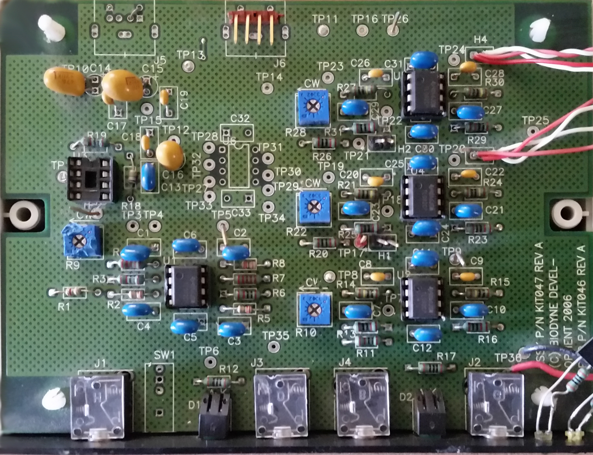
Light-emitting diodes (LED’s) were attached to the input, the output of the first stage and the output of the second stage (see image above). These LED’s light when the signal amplitude reaches its peak. The LED on the far left (labeled “Input”) is connected to the signal input, the one in the middle (labeled “1”), to the output of the first stage, and the one on the right (labeled “2”), to the output of the second stage.
SA circuitry in operation: the temporal advance of the input pulse is clearly visible. Note the order in which the LED’s appear. The first to light is LED “2”, (output – second stage), followed by LED “1” (output – first stage) and then the “Input” LED.
Above is a time-lapse video of a dual-trace oscilloscope (timescale: 0.5 s/div) showing the temporally advanced output pulse (output from the second SA circuit stage) relative to the input. The temporal advance achieved was just under 0.5 s, per circuit stage, giving an overall time advance of nearly a second. Note the output distortion (narrowed pulse width and skewing) relative to the input.
These preliminary results efforts convincingly demonstrated that a signal temporal advance design using NGD can be implemented in electronics, and indicated the following:
- the ability to cascade SA circuit stages to increase the overall time, and,
- the need for signal conditioning to reduce signal distortion in the advance output.
Continue to Wave Propagation Physics.